
This is the second post in a series that aims to document the process of building a Gigatron retro gaming computer which uses logic chips instead of an existing microcontroller in order to explore what each part of a general purpose computer does and how it works.
You can see the first introduction post in the series here: https://blog.withcode.uk/2023/05/how-do-computers-work-part-1-introduction/
Walter Belgers has created an excellent instruction booklet for assembling the Gigatron computer which is shared under the Creative Commons Share Alike Attribution licence, which I’ll refer to regularly throughout this series. The first 29 pages are a brilliant introduction to electronics and soldering which are well worth reading through.
The practical step starts on page 30 which involves inserting and soldering 40 capacitors which you can see Walter demonstrate here:
Today at Game Dev Club I had three volunteers who soldered a couple of capacitors each. I’m not going to mention student names on this public blog but it was soon pretty apparent that some of them were better at soldering that others (most were better than me to be fair)!
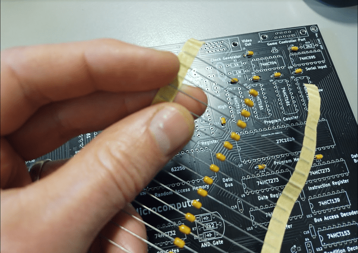
It took us a while to get used to using the soldering iron properly: it really helps to heat up both the metal pad on the PCB (printed circuit board) and the pin / leg of the component before applying any solder, so that the solder will flow smoothly onto all of the hot metal parts in order to make a good electrical connection.
What is a capacitor?
We only got through 6 of 40 capacitors in today’s Game Development Club. It looks like there is one next to the space on the PCB (printed circuit board) for each IC (integrated circuit), labelled C5 to C45
A capacitor stores electrical charge like a mini battery. It can be used to smooth or filter out unwanted electrical signals. Page 12 of the assembly guide shows the symbol used to represent different types of capacitors:
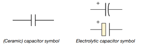
“Capacitors come in all shapes and sizes, but they usually have the same basic components. There are the two conductors (known as plates, largely for historic reasons) and there’s the insulator in between them (called the dielectric). The two plates inside a capacitor are wired to two electrical connections on the outside called terminals, which are like thin metal legs you can hook into an electric circuit.”
Source: https://www.explainthatstuff.com/capacitors.html
The different types of capacitor reflect the way that they are assembled. The 40 capacitors we need to solder are all 100nF (100 nano Farad) ceramic capacitors. 100nF is the same as 0.1µF (0.1 micro Farad, or 0.0001Farad).
The schematic (high level circuit diagram) shows that these capacitors are used
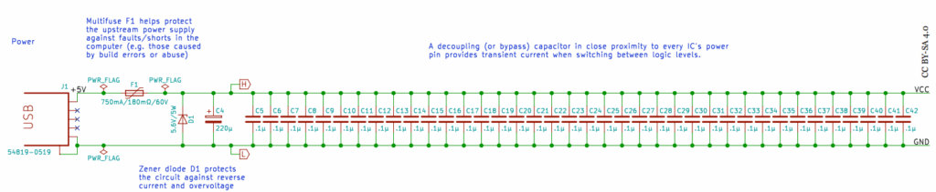
This circuit diagram shows most of the 40 capacitors (C5-C42) connected to GND (ground, 0v) and VCC (Voltage Common Collector, 5v). Each capacitor is located really close to a TTL logic IC (Transistor to Transistor Logic Integrated Circuit). The purpose of each IC is to switch an electronic signal on or off like a digital switch in order to make up the logic of the way the computer processes data. When these digital switches change from on to off or vice versa, it’s helpful to have a capacitor close by (within 5-10mm) to act as a mini power supply to smooth out a spike in electrical current. Sparkfun electronics explains this better than I can here.
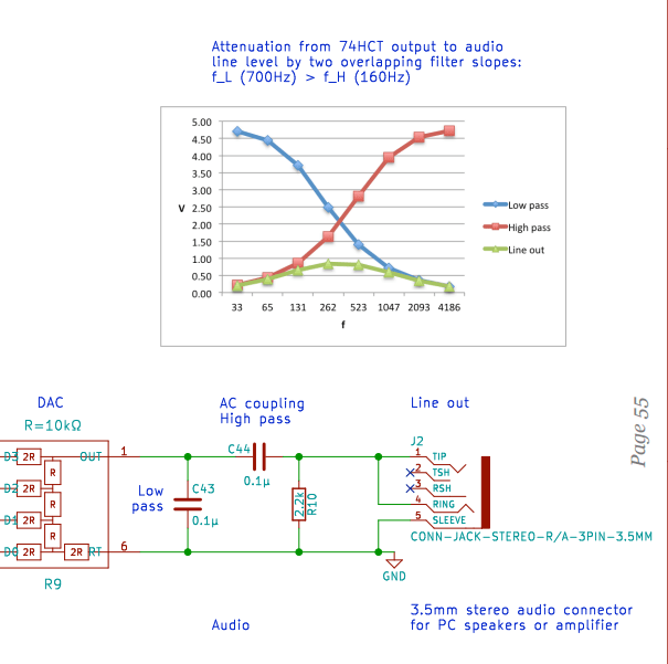
The other 0.1µF capacitors are used to filter out low frequency (bassy) and high frequency (squeaky) sound from the audio output. I haven’t got as far as soldering those yet…:
When we’ve eventually finished soldering in all of the capacitors, the next step will be to solder and test the components that provide a stable power supply.


