This is the third post in a series that aims to document the process of building a Gigatron retro gaming computer which uses logic chips instead of an existing microcontroller in order to explore what each part of a general purpose computer does and how it works.
You can see the first introduction post in the series here: https://blog.withcode.uk/2023/05/how-do-computers-work-part-1-introduction/
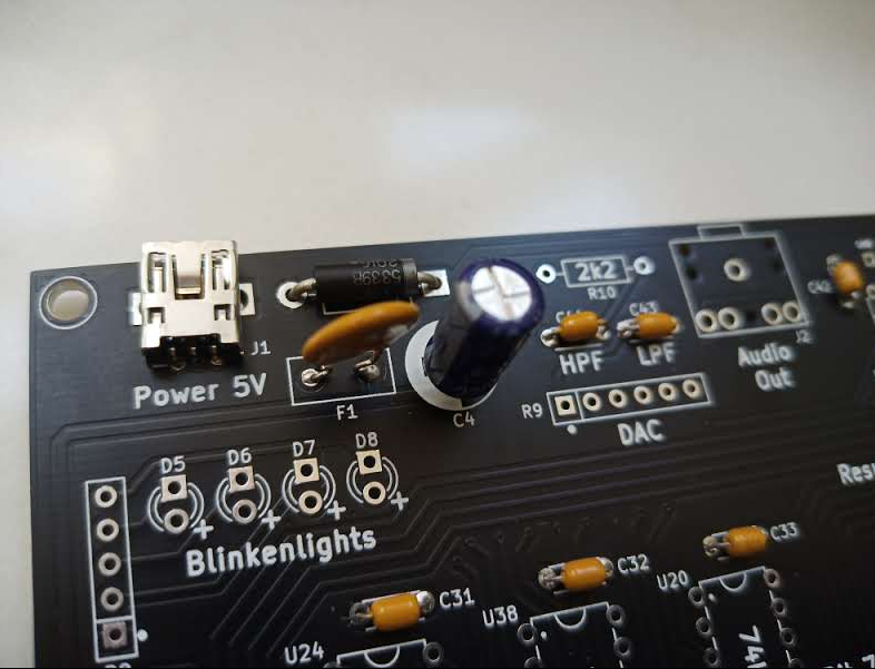
Now that I’ve got all of the capacitors soldered next to where the logic ICs will go, the next step is to assemble and explore how the power supply will work.
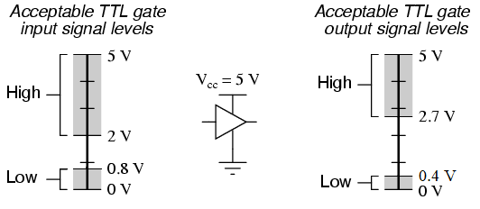
Transistor-Transistor-Logic (TTL) Integrated Circuits (ICs) need 5v to operate. In a digital design, we’d like to work with just two binary states: 1 and 0, represented by switching 5v on or off (0v). In reality, there’s an infinite variety of voltages between 0v and 5v but a digital device needs to be able to draw the line somewhere in order to accurately, predictably and reliably use electrical signals to store, process and transmit the binary data and instructions that makes up the building blocks of digital computers.
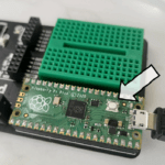
In order to provide a reliable power supply to all of the TTL ICs that form the logic that makes the Gigatron computer work, it gets 5v from a USB connector. The data pins of the USB connector aren’t used or connected to anything so the Gigatron could be powered from a rechargeable battery pack if necessary (although most of the ones I have switch off automatically after a minute or so unless it thinks something is connected, and the Gigatron doesn’t draw enough current to fool the power bank into staying on).
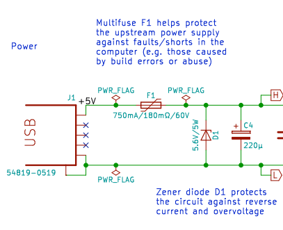
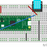
In theory, getting power from USB means we should always get 5v (not -5v and not a spike of mains power like 230v) but (perhaps knowing my capacity to solder things the wrong way round) the Gigatron designers have included a diode (D1) and multifuse just in case. Diodes only conduct electricity in one direction so if everything is connected the right way, no current flows through the diode. If the polarity of the power supply is reversed (connected the wrong way round) then the diode conducts electricity and all the current flows, with through the multifuse. Normal fuses are designed to melt (and so break the circuit to stop electricity flowing) when too much current flows. That’s annoying because you have to replace them. The multifuse will get hot if too much current flows which will break the circuit until it cools down.
I’ve learnt something there – I thought the multifuse (labelled F1 in the diagram above) was a large capacitor. There is a capacitor in the power supply circuitry: a much bigger capacitor (both physically and in terms of how much charge it can store) than the 0.1µF ones previously soldered (e.g. C31). C4 is a 220µF electrolytic capacitor which is used to smooth out any ripples in the power supply. Ripples might come from the 50Hz oscillations (high / low waves) from mains powered devices and they could potentially change a High (5v) digital signal to accidentally interpreted as a Low (0v) signal (or vice versa) causing errors which are really hard to detect or reproduce.
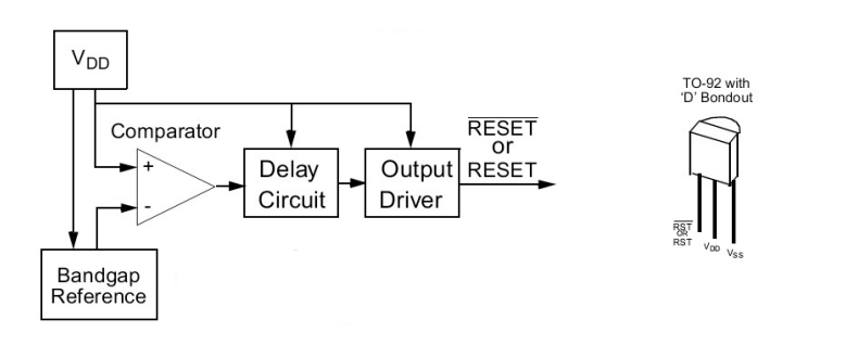
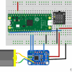
The other part of the power supply circuitry is an LED (with a resistor to prevent too much current to the LED) and a supervisory circuit which looks like a transistor (labelled U2 below):
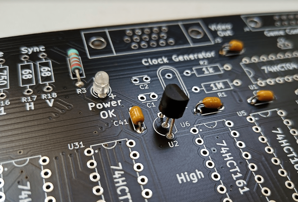
I’ve taught students that when a CPU switches on there are certain things that need to happen right away but I’ve never know before what actually triggers that start-up sequence. The supervisory circuit is the part that detects when the power supply is first switched on (and so sends a signal to the logic to set the program counter register to zero so the first program can start from the beginning) and waits until the power supply has stabilised before starting the normal fetch / decode / execute sequence that a CPU does for the rest of its time.
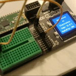
At this point, I’ve got enough working to be able to plug in a USB cable and hope that the LED switches on (hooray – it does!).
To celebrate, I watched this video with my Y12s where Walter Berger talks through the design decisions and their implications that he and Marcel van Kervinck made whilst designing the the Gigatron.
This video is gold dust for A Level Computer Scientists. My students started their course learning about the structure and function of a processor, then explored RISC vs CISC and Von Neumann vs Harvard and they’re currently looking at the different stages that a compiler goes through to translate high level program code (like C#) into executable machine code. This video gives the context and application that join all of those topics together in a fascinating and brilliant way. I think so anyway…
Now that we’ve got a stable power supply, the next step will be generating a clock signal to synchronize and control everything that the computer does.


