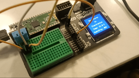
Adventures with Electronics is a father and son project to learn how to connect up and code 37 different electronic sensors using a Raspberry Pi Pico.
Kit:
Prices and links are indicative: other suppliers may have better deals. No affiliate links.
- 37 Sensor Kit from Elgoo: It looks like the version I have isn’t for sale any more. The ‘upgraded version’ available on amazon has slightly different sensors. This looks the same as the version I have just in a different box or bag
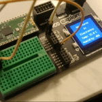
- Raspberry Pi Pico Explorer board with a screen, buttons, and breadboard:
- Male to male cables to plug in different sensors:
Software:
You can find all the resources for the Adventures in Electronics tutorials on this GitHub repository which contains:
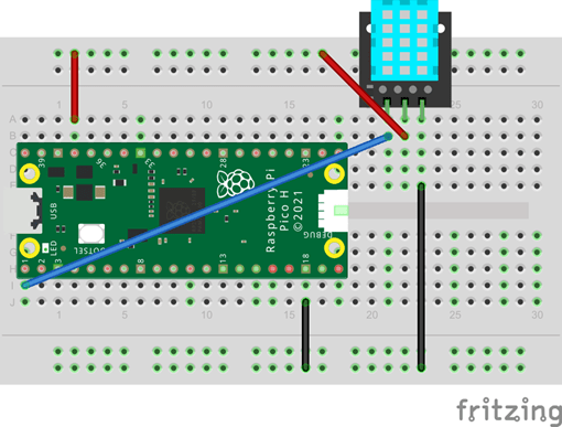
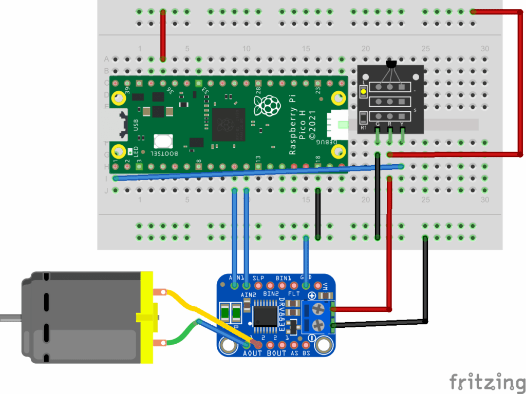
- Fritzing models to create circuit diagrams
- Example code in circuitpython and micropython. The videos show the circuitpython code which uses the screen on the pico explorer board but the micropython code will work if you just have a raspberry pi pico without the pico explorer board
- Datasheets
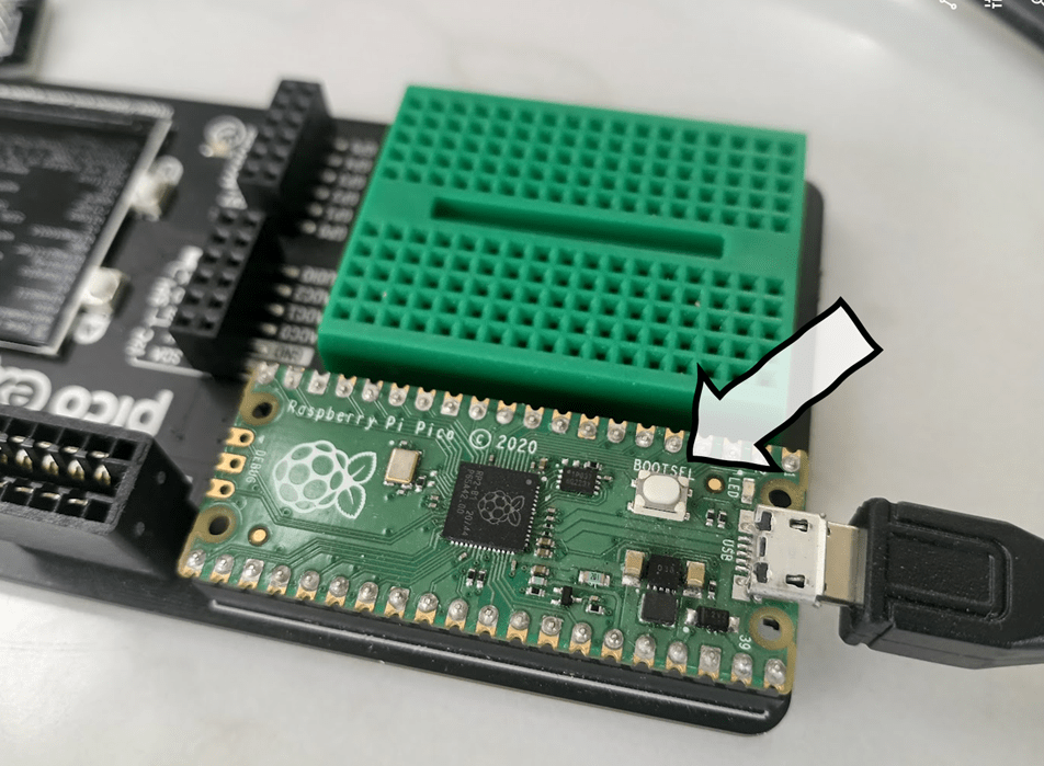
Getting Started
This post talks you through how to set up the hardware, software and firmware needed to kickstart your adventure in electronics: you’ll need to do this before you start writing any python code.
Sensors
The plan is to work through each sensor in the pack of 37 in the order shown below:

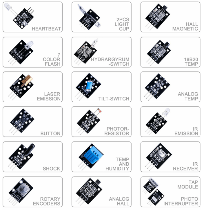
- DHT11 Digital Humidity and Temperature sensor
- DS18B20 Temperature sensor module
- Button switch module
- Two shock switch module
- Two tilt switch module
- IR Receiver and IR Transmitter
- Active buzzer module
- Passive buzzer module
- Laser module
- SMD RGB module and RGB module
- Photo interrupter module
- Dual colour common cathode LED
- Light Dependent Resistor module
- Large microphone module and small microphone module
- Reed switch and mini reed switch modules
- Digital temperature module
- Linear hall and analog hall module
- Flame sensor module
- Though sensor module
- Seven colour flash module
- Switch light module
- Joystick module
- Line tracking module
- Obstacle avoidance sensor module
- Rotary encoder module
- Relay module
- Heartbeat sensor module


