Running your first program
Now that everything’s set up and ready to go, let’s write, compile and run the following program:
void setup() {
  // put your setup code here, to run once:
  Serial.begin(115200);
  Serial.println("Hello world");
}

int count = 0;
void loop() {
  // put your main code here, to run repeatedly:
  Serial.println(count++);
  delay(1000);
}
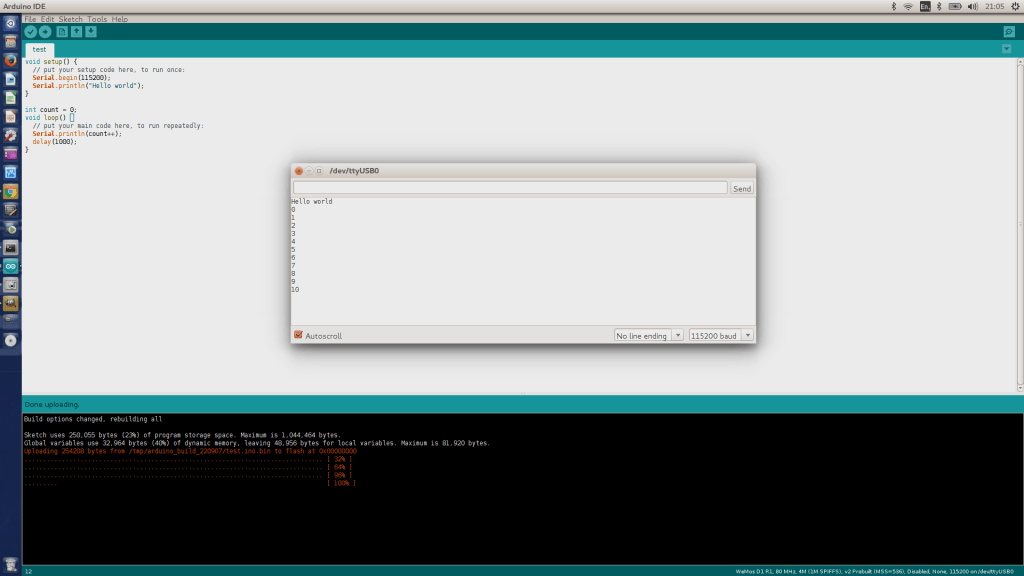
- Copy and paste the above code into the Arduino IDE then press the upload button (top left, looks like an arrow pointing right).
- While you wait for it to compile and upload to your device, open the Serial Monitor (Ctrl + Shift + M) or Tools > Serial Monitor
- All being well you should see the following:
Whilst there is a screen on the device, it take a bit of work to display stuff on it so the easiest way to see if anything is working is to send a message via the USB cable back to your desktop / laptop.
The setup()function starts by initialising the serial port. 115200 is the speed at which data is sent down the USB cable. As long as it’s set to the same number as you’ve set in the Arduino IDE it should work.
Above and outside of the loop()function is a variable called count which is used to count up from 0 every second.
The ++increases the value stored in this count variable by one and the delay(1000)pauses the code by 1000ms (1s) so it doesn’t run too quickly.
If it doesn’t work, there’s a good chance you’ve missed a ;off the end of a line or you’ve got the settings wrong to connect to your device (see the previous page)
Even if that all works, it’s not a very exciting program yet because the device doesn’t actually do anything visible in its own right.
The following program still sends a number down the USB cable so you can see that it’s working but it also flashes the builtin LED on the device itself (mine’s blue and located just next to the silver square ESP8266 chip):
void setup() {
  // init serial port
  Serial.begin(115200);

  // send message down USB cable
  Serial.println("Hello world");

  // set the builtin LED pin to work as an output
  pinMode(LED_BUILTIN, OUTPUT);
}

int count = 0;
void loop() {
  // increment count and send it down USB cable
  Serial.println(count++);

  // flash the LED
  digitalWrite(LED_BUILTIN, HIGH);
  delay(500);
  digitalWrite(LED_BUILTIN, LOW);
  delay(500);
}




thank you very much for your help 🙂 I couldnt make it work without that
Hiyah!
The directional buttons: FLATH, RSET, D5, D6, D7
What on earth is FLATH?
Also – won’t RSET reset the board when the “direction” is pressed on the little joystick?
Yes, because of the way the joystick is connected up, the board will reset when you press left. I don’t know what FLATH is: it’s on all the description pages when you try to buy it but the joystick is actually connected to D3,D5,D6,D7 (and RSET). Maybe there’s a way to disable the reset-not sure-sorry!
I’m pretty sure FLATH is nothing but a typo from the first and original description (that has been copied wrongly every time)
This is the FLASH button. In order to FLASH another binary (firmware) this button has to be pressed while turning power ON.