Using the OLED screen
From searching similar product description pages to the device I ordered, it seems that the device I’ve got has a 0.96″ black and white OLED screen which is controlled using an I2C bus on pins D1 and D2 for SDA (the data line) and SCL (the clock line) respectively.
Multiple devices can share the same I2C bus, each with their own address, so we first need to scan each possible address to see if there’s anything connected to it.
Here’s the code I used to discover the address of the OLED screen:
#include<Wire.h>

void scanI2C(byte start, byte stop) {
  byte error;
  Serial.println("Starting scan");
  for(byte address = start; address < stop; address++) {
    Wire.beginTransmission(address);
    error = Wire.endTransmission();
    if(error == 0) {
      Serial.print("Device found at 0x");
      if(address < 16)
        Serial.print("0");
      Serial.println(address, HEX);
    }
  }
  Serial.println("Scan complete");
}

void setup() {
  // init I2C bus on pins D1 and D2
  Wire.begin(D1, D2);

  // init serial port
  Serial.begin(115200);

  Serial.println("Scanning I2C bus to find display...");

  // scan all 127 addresses
  scanI2C(0, 127);

  // set the builtin LED pin to work as an output
  pinMode(LED_BUILTIN, OUTPUT);
}

void loop() {
 digitalWrite(LED_BUILTIN, HIGH);

 delay(1000);
 digitalWrite(LED_BUILTIN, LOW);

 delay(1000);
}
When I run this, I get the following output in the Serial Monitor (Ctrl + Shift + M):
Scanning I2C bus to find display...
Starting scan
Device found at 0x3C
Scan complete
Getting to this point took me a long time – the key thing that got it to work for me was updating the ESP8266 board manager plugin to 2.4.0-rc2 rather than 2.4.0 which allowed the I2C bus to run on pins other than the default ones for the Wire library (in this case pins D1 and D2)
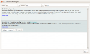
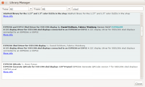
To get your device to speak to the OLED screen you need to download two libraries using Sketch > Include Libraries > Manage Libraries and install the two libraries selected below:
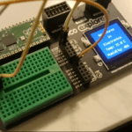
Now it starts to get exciting: the code below will display the text “The screen is working”, starting at the top of the screen but falling down by 1 pixel each time the LED flashes.
#include <OLEDDisplay.h>
#include <SSD1306.h>

// connect to display using pins D1, D2 for I2C on address 0x3c
SSD1306  display(0x3c, D1, D2);

int y;

void setup() {
  // init serial port
  Serial.begin(115200);

  // set the builtin LED pin to work as an output
  pinMode(LED_BUILTIN, OUTPUT);

  // init the display
  display.init();

  // set text y coordinate to start at 0
  y = 0;
}


void loop() {
  // turn off the LED
  digitalWrite(LED_BUILTIN, HIGH);
  delay(100);

  // clear the screen
  display.clear();

  // display text on the screen
  display.setTextAlignment(TEXT_ALIGN_LEFT);
  display.setFont(ArialMT_Plain_10);
  display.drawString(0, y%64, "The screen is working!");

  // move text down 1 pixel next time
  y++;

  // update the display
  display.display();

  // turn on the LED
  digitalWrite(LED_BUILTIN, LOW);
  delay(100);
}





thank you very much for your help 🙂 I couldnt make it work without that
Hiyah!
The directional buttons: FLATH, RSET, D5, D6, D7
What on earth is FLATH?
Also – won’t RSET reset the board when the “direction” is pressed on the little joystick?
Yes, because of the way the joystick is connected up, the board will reset when you press left. I don’t know what FLATH is: it’s on all the description pages when you try to buy it but the joystick is actually connected to D3,D5,D6,D7 (and RSET). Maybe there’s a way to disable the reset-not sure-sorry!
I’m pretty sure FLATH is nothing but a typo from the first and original description (that has been copied wrongly every time)
This is the FLASH button. In order to FLASH another binary (firmware) this button has to be pressed while turning power ON.