CPUs work by following the fetch decode execute cycle.
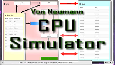
Von Neumann CPU Simulator showing the fetch decode execute cycle
At Key Stage 3, students in the UK need to have a good idea of the process as a whole:
The fetch decode execute cycle is the loop that CPUs constantly follow in order to get, understand and do each instruction in a program.
At Key Stage 3, students need to understand the role of different parts of a CPU in the Von Neumann model.
A Von Neumann CPU has one memory store (RAM) which stores both data (variables) and instructions (program code).
Registers are fast but small memory locations that can store one item of data or one instruction.
The Little Man Computer model is popular at both Key Stage 3 and Key Stage 4 because it simplifies what happens inside a CPU down to just three registers: an instruction register, an accumulator and a program counter with a very limited instruction set.
For A Level, some additional components have to be understood which makes the Little Man Computer model appear too limited to be used to explain all of the necessary theory. Students also need to be able to explain the purpose and function of:
- The Memory Address Register (MAR) and Memory Data Register (MDR)
- The Address Bus, The Control Bus and the Data Bus.
To help fill those gaps, I’ve built a CPU simulator based on the diagram shown in the Craig’n’Dave video below:
The simulator lets you enter in any values into the memory store (as binary, denary or hex) and then either run the whole code or step through each stage in the fetch decode execute cycle.
You can try the simulator here or download the source here.
This tool is designed as a teaching aid to allow teachers and students to step through each line in a binary computer program with an explanation of what each register and bus is doing at every stage.
I hope it’s useful. Let me know if you spot any mistakes or ideas for improvement.


This is excellent!!